LOD 300 Architectural & Structural BIM Modeling: Geometry, Permits & Fee Benchmarks
Design-development and permit-grade 3D BIM geometry with verified wall assemblies, structural column/beam sizing, and code-compliant egress schedules.
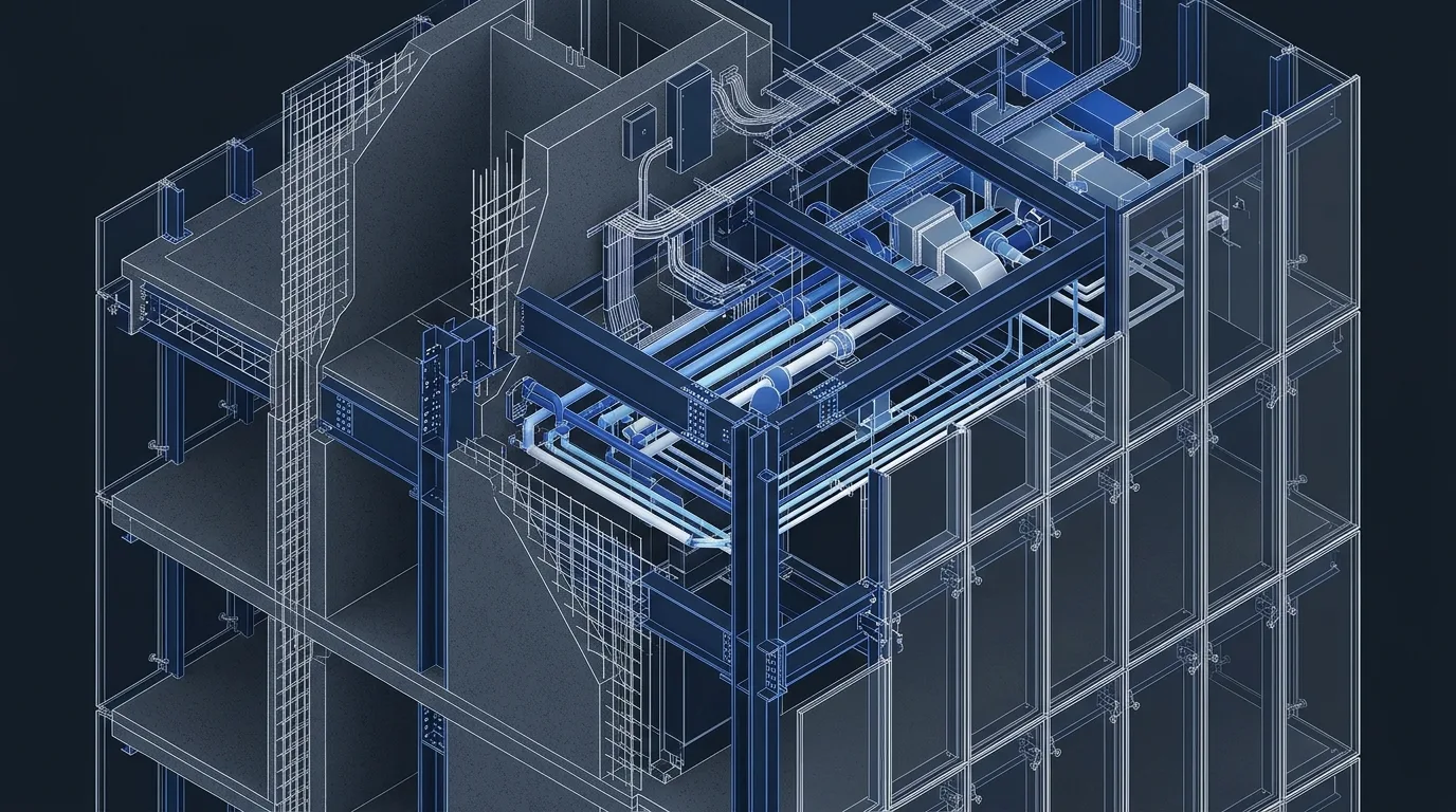
Technical Parameters & Tolerance Matrix
| Engineering Parameter | Specification Benchmark |
|---|---|
| Target BIM Level & Governing Norm | LOD 300 · ISO 19650 · AIA G202 LOD 300 · RIBA Stage 3 |
| Reference Gross Scale | 2,500 – 15,000 m² |
| Coordinated Disciplines | Architectural + Structural Primary Frame |
| Milestone Delivery Schedule | 2 – 4 Weeks |
| Indicative Studio Fee Band | $11,500 – $22,000 (for 5,000 m² ref.) |
| Native File Deliverables | .RVT · .IFC4 · 2D Permit .DWG / PDF |
Project & Engineering Scope Overview
LOD 300 Architectural & Structural BIM converts conceptual sketches or 2D CAD drawings into dimensionally verified 3D building elements—establishing exact wall thicknesses, floor-to-floor heights, structural slab edges, and statutory area schedules.
Engineered to LOD 300 precision across a reference benchmark of 2,500 – 15,000 m² under ISO 19650 · AIA G202 LOD 300 · RIBA Stage 3, this canonical specification unifies spatial design, multidisciplinary clash resolution, and 5D cost certainty prior to site mobilization.
Architectural Layout, Structural Grid & Spatial Zoning
Structural Grid & Modular Alignment: Primary structural axes (6.0 m – 8.4 m typical spans) aligned with subterranean parking bays and vertical elevator/stair cores.
Primary column grids, facade mullion subdivisions, and subterranean parking geometry are locked onto a unified datum—eliminating non-standard off-cuts and costly site framing adjustments.
Functional Area Program & Net-to-Gross Floor Plate Optimization
Spatial Program & Net-to-Gross Efficiency: Gross-to-net floor efficiency audited via live Revit Area Plans, locking statutory FAR/massing envelopes and compartment boundaries.
Live parametric Revit area schedules track net usable/leasable floor area against vertical cores, MEP plantrooms, and envelope wall thickness at every design iteration.
Circulation Cores, Logistics Access & Life-Safety Egress
Vertical Cores, Logistics & Life-Safety Egress: Code-verified corridor widths, stair riser/tread geometry, ramp gradients (≤8%), and maximum fire travel distances.
Travel distances, pressurized stair cores, ADA/accessible routing, and heavy service/loading dock swept-path geometry are validated against NFPA, EN, and local building regulations.
Site Utilities, Stormwater Drainage & Wet-Shaft Engineering
Subsurface Utilities, Drainage & Wet Shafts: Dedicated vertical wet risers and primary roof rainwater outlets sized and reserved inside structural slab zones.
Gravity stormwater and foul drainage stacks are modeled with true 1.5%–2.0% invert slopes, locking structural beam web penetrations and acoustic riser sleeves before rebar detailing.
Plumbing, Fire Suppression (NFPA / EN) & Hydronic Piping BIM
Domestic Plumbing, NFPA/EN Sprinkler & Hydronics: Fire pump room footprint, water tank volumes, and main riser shafts spatially locked for authority submission.
Wet/dry sprinkler grids, fire hose cabinets, booster pump skids, and hydronic manifolds are spatially coordinated above ceiling plenums without compromising architectural clear heights.
HVAC Climatic Routing, Acoustic Control & Zero-Clash MEP
HVAC Routing, Acoustics & Zero-Clash Verification: Primary mechanical plantrooms, roof AHU/chiller zones, and main vertical shaft clear-openings reserved with zero structural conflict.
Automated Navisworks and Solibri rule-sets enforce ±3 mm hard-clash tolerances and 25–50 mm insulation/maintenance clearance zones, closing 100% of BCF issues prior to tender issue.
Structural Steel / RC Framing & Seismic Performance Analysis
Structural Framing & Seismic Engineering: Preliminary finite-element sizing of RC columns, shear walls, foundations, and primary steel girders per Eurocode / TBDY 2018.
Inter-story seismic drift ratios, ductile steel moment/braced connections, foundation punching shear, and secondary facade subframes are signed off by our senior structural engineering partners.
Facade Envelope, Roof Assembly & Hygrothermal U-Value Detailing
Building Envelope & Hygrothermal Physics: Multi-layer exterior wall and roof types defined with target thermal transmittance (U-values) and glazing window-to-wall ratios.
2D/3D thermal-bridge condensation risk is audited per EN ISO 6946, pairing Class A1 mineral-wool insulation, vapor-permeable membranes, and slotted seismic facade brackets at 1:5 shop detail scale.
Georeferenced Site Plan & ISO 19650 Common Data Environment (CDE)
Georeferenced Masterplan & ISO 19650 CDE: Georeferenced site topography, property setbacks, and shared survey coordinates configured per ISO 19650-2.
All discipline models share true survey coordinates (UTM / National Grid) and progress through ISO 19650 WIP → Shared → Published gates inside the Common Data Environment.
BIM & Construction Document Deliverables (.RVT / .IFC4 / .NWD / .DWG)
Native BIM & Construction Documentation Package: Clean workshared Revit (.RVT) architectural and structural models, IFC4 Reference View exports, and 1:100 / 1:50 permit drawing sets.
Clients receive unlocked native .RVT · .IFC4 · 2D Permit .DWG / PDF source files, plotted PDF/DWG construction sets, and signed zero-clash audit certificates.
5D Quantity Take-Off (BoQ), Studio Fee Band & Cost Benchmarks
5D Quantity Take-Off (BoQ) & Indicative Studio Fee: The indicative engineering & BIM fee band for this reference scope is $11,500 – $22,000 (for 5,000 m² ref.) (with indicative construction CAPEX benchmark at $6.0M – $9.2M Construction Ref.). Provides elemental quantity schedules (m² facade, m³ concrete, gross floor plates) achieving ±8% early cost-plan accuracy.
DfMA Prefabrication, 40HC Export Packaging & Execution Pathways
DfMA Prefabrication & Export Execution Pathways: Establishes modular structural bay repeatability early so downstream LOD 350/400 prefabrication proceeds without grid redesign.
Clients may tender the open BIM package to any local contractor or leverage our integrated group factories (SerBuild steel structures, SerMimar İskele EN 12810 scaffolding, SerMimar Şömine hearths, and SerSourcing 40HC consolidation).
International Building Codes, Green Certification & Grant Readiness
International Codes, Sustainability & Compliance: Full alignment with RIBA Stage 3 Spatial Coordination, German HOAI LP 3–4, AIA Design Development, and municipal zoning codes.
Structured directly for LEED / BREEAM / RE2020 energy modeling, UK Building Safety Act Golden Thread compliance, Eurocode National Annexes, and institutional lender due diligence.
BIM, Masterplan & Facade Scope Calculator
- .RVT + Tekla/Structural IFC
- Seismic Calculation Report
- .DWG Structural Set
Related Engineering Packages & Typologies
Explore complementary BIM levels, building typologies, and facade/DfMA specifications.
LOD 350 4-Discipline BIM Coordination
Construction-ready RIBA Stage 4 federated coordination modeling exact structural connections, MEP hangers, slab penetrations, and zero-clash ceiling plenums.
LOD 400 Fabrication & Shop Drawing BIM
Direct-to-factory digital twins containing bolt/weld assembly marks, MEP prefabrication spool sheets, curtain-wall machining details, and zero-waste cut lists.
Architectural Construction Documentation (CD Sets)
Comprehensive RIBA Stage 4 / HOAI LP 5 / AIA Construction Document sets generated directly from coordinated 3D BIM models—plans, wall sections, wet-cores, stairs, and schedules.
Frequently Asked Engineering & Commercial Questions
Direct technical answers on deliverables, ISO 19650 workflows, revisions, and fee structures.
When is LOD 300 the right choice instead of LOD 350 or LOD 400?
Can an LOD 300 model be upgraded directly to LOD 350/400 later without remodeling?
What input files do you require to start an LOD 300 BIM package?
Are doors, windows, and room finish schedules dynamically linked in LOD 300?
How fast can you deliver an LOD 300 permit BIM package for a 5,000 m² building?
Request a Scoped BIM, Masterplan or Facade Engineering Proposal
Share your site parcel, CAD sketches, or point-cloud survey directly with our founding architects and civil engineers. Receive an itemized LOD deliverables matrix and fixed milestone schedule within 24 hours.